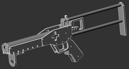
The +Bow (PlusBow) |
| Main Project Aim: Develop a homemade version of the Crossbow that has performance comparable to one modified to level 4. Due to increasing rarity and cost of obtaining them in decent condition, I will be making full construction plans available.
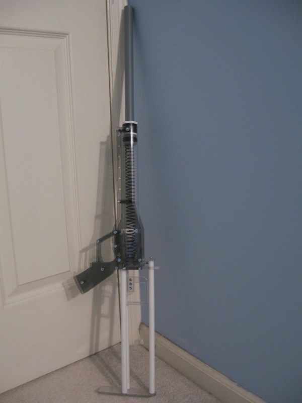
Secondary Project Aim: Integrate a rail attachment system to allow integrations to be mounted on the gun using adapter brackets and quick-release pins making the base weapon adaptable to the needs of different play types. Also work to reduce part count, simplify construction, reduce build cost, and make the gun as easy to service and repair as possible. Gun can easily and quickly be broken down into 3 or 4 subassemblies for shipping or transportation to wars. Specifications Length: 36 inches Weight: 2lb Plunger load: 18-32lb Spring load maximum: 38lb Optimal Barrel Length: 12 inches Performance Plunger rod has three notches affording different load rates which gives the user different range options. Distances averaged 28lb Pull: 140 feet 22lb Pull: 110 feet 16lb Pull: 80 feet Individual results will be dependent upon too many factors to list so take these only at face value. Accuracy has been extremely good using only the iron sight designed into the rear frame piece. I've been able to hit moving targets from 80 feet away without too much difficulty. However it does help that I also have very accuract darts. Nerfhaven Forum Thread Video on Youtube If you have any question you can contact me through: captainslg@aol.com |
Construction |
|
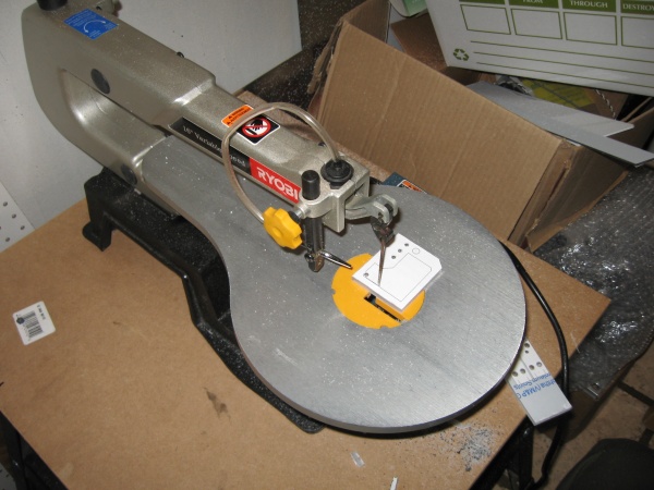
Essential Tools + Scrollsaw + PowerDrill or Drillpress + Mitre Box & Mitre Saw or a power tool useful for cutting plastic rod or tube (such as a table saw, circular saw, or band saw) + #6-32 Tapping Bit + Screwdriver + Hobby Knife (to clean the edges of the sheets once cut) + Scissors + Inkjet printer + Packet of full-sheet label paper + Electrical tape Make the process easier + Table Saw + Band Saw + Drillpress No other tools expressly needed. All tools listed are not easily substitutable and I don't recommend attempting to make this gun with anything other than a scrollsaw due to the size of the parts you will be making. Part List Download: plusbow_partlist.txt All items available through http://www.mcmaster.com Simply search for the part #s listed. Total cost of supplies listed is around $80 plus shipping. You will have enough excess of most materials to make atleast 2 or 3 more guns. |
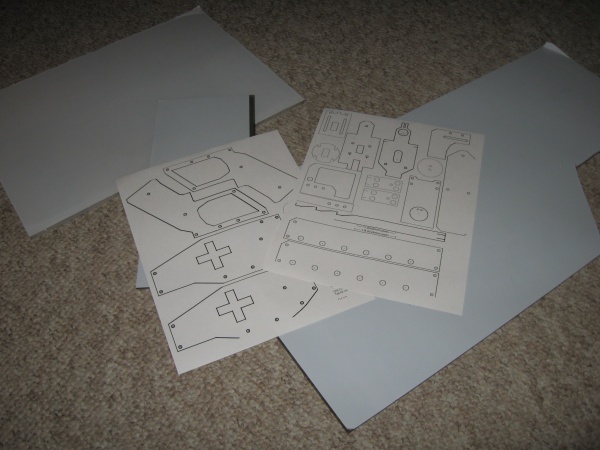
Step One |
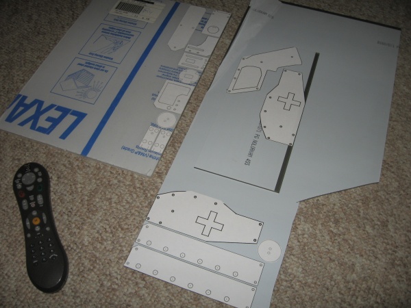
| Download the cuttings template sheets: plusbow_templates.doc (100kb) Print them on full sheet label paper. If you ran out of color ink (like I did) make sure to use a colored pencil to mark the holes with the size you will need to drill them to. |
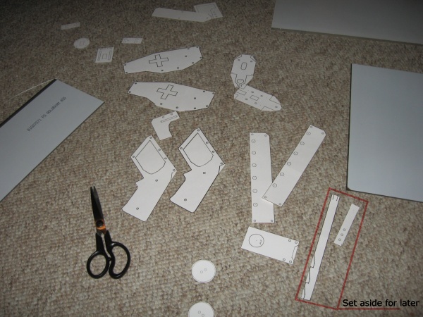
Step Two |
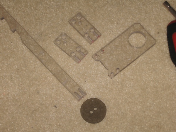
| Cut out all of the templates from the full sheet. Set aside the labels indicated in the picture because you won't be applying them right away. They will have to be applied to the opposite ends of the 13.25 x .5" length piece of 1/4" thickness polycarbonate that will become the plunger rod. You can cut this out now or later using a scroll saw or table saw after marking the dimensions. |
Step Three |
| Apply the cutting templates to the indicated thicknesses of polycarbonate sheet. You can group them fairly close together to minimize excess, but keep enough of a gap to allow the blade of the scrollsaw to cut inbetween the parts. |
Step Four |
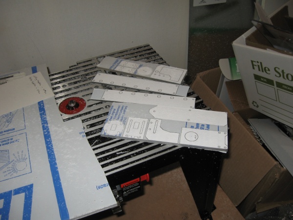
| Cut the labeling sheets into smaller more manageable sections using a scroll saw or band saw. Wait to cut out all of the small parts until later. This will make drilling holes in the smaller pieces much easier and safer. |
Step Five |
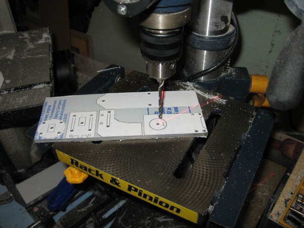
| Using a drillpress or power drill follow the color legend you printed or wrote on the labels to drill out all of the holes to the required sizes. Also make sure to drill 5/32" diameter pilot holes in the center of the areas you will have cut out. Such as the pass-through holes in the frame pieces and catch plate, The slide tracks in the trigger and catch plate, the trigger wells in the sides of the grip, the center of the priming handle, and the optional decorative "+" signs on the body sides |
Step Six |
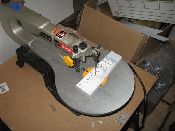
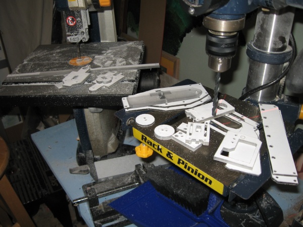
| Use a scroll saw or band saw to make all of the external cuts needed to free and shape all of the parts out of the sheet. |
Step Seven |
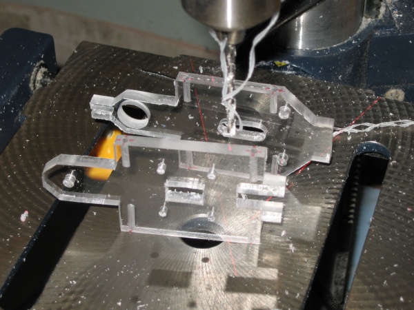
| Use a scroll saw to make all of the internal cut outs. Start by feeding the blade through the pilot hole you drilled in Step Five then retentioning the blade. |
Step Eight |
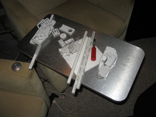
| Now all of your plastic sheet parts are cut out. |
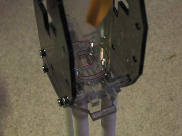
Step Nine |
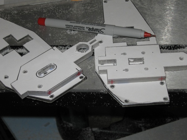
| Using the side plates that they will eventually screw into as a guide, mark the edges of both sides of the frame pieces as shown. |
Step Ten |
| Using a 7/64" bit in a drillpress or power drill drill to a depth of around 1/2 of an inch. Then tap the holes with a UNC #6-32 tapping bit. |
Step Eleven |
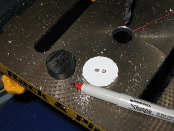
| Using a mitre saw with box, table saw, band saw, or circular saw cut a 7/16" length section off of the 1" diameter plastic rod. Using the 1/8" thickness plunger rod piece as a template (as centered as you can get it), mark the two holes as shown. Using a 5/32" bit in a drillpress or power drill drill through at the marked points. |
Step Twelve |
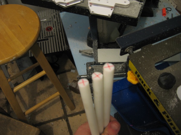
| Using a mitre saw with box, table saw, table saw, or circular saw cut two 11-1/4" length sections and one 12" length section off of the 1/2" diameter plastic rod. Mark the center of both ends of the rods. Using a 7/64" bit in a drillpress or power drill drill to a depth of around 1/2 of an inch. Then tap the holes with a UNC #6-32 tapping bit. |
Step Thirteen |
| Remove the cutting templates and protective film from the plastic sheet parts. The catch plate will need its lower edge beveled and the corners of the stub at the top beveled to accept a spring. To see more detail on this part see Step Seventeen and Step Eighteen. |
Step Fourteen |
| Deburr the edges of all of the sheets using a hobby knife To quickly remove the burrs simply orient the blade perpendicular against the edges of the sheet and run it along them. Any trouble spots and be cleaned with the hobby knife by manually cutting away the burrs. Further smoothing can be done with sandpaper if desired. I would recommend doing so on the grip. |
Step Fifteen |
| Using the 1/8" thickness plunger rod part as a template, mark the front edge of the plunger rod. Using the front piece of the adapter bracket, do the same on the front edge of the side pieces for the adapter bracket. Using a 7/64" bit in a drillpress or power drill drill to a depth of around 1/2 of an inch. Then tap the holes with a UNC #6-32 tapping bit. |
Step Sixteen |
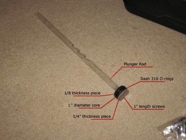
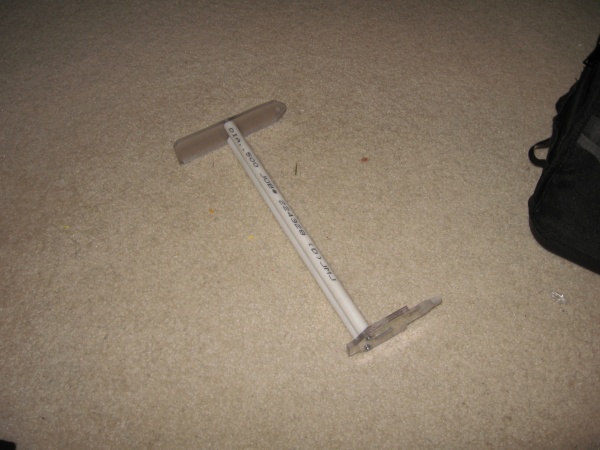
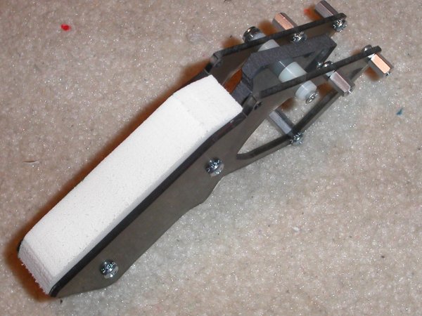
| Squeeze two Dash 316 O-Rings onto the 7/16" section of 1" diameter plastic rod. Sandwhich it inbetween the 1/8" and 1/4" thickness plunger head pieces and bolt them onto the end of the plunger rod using 1" length screws. |
Step Seventeen |
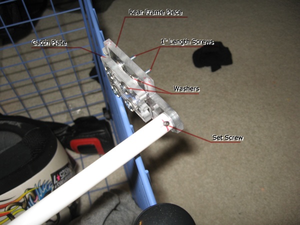
| Assemble the center frame piece and catch plate together as shown using washers and 1" length screws. Attach the 12" length section of 1/2" diameter rod to the center frame piece using a 3/8" length screw. Mark on it where the centerline of the catch plate is. Remove the 12" rod and using a 7/64" bit in a drillpress or power drill drill through where marked. Then tap the hole with a UNC #6-32 tapping bit. Attach the 12" length rod to the rear frame piece again using a 3/8" length screw. Install a set screw into the newly tapped hole by hand. |
Step Eighteen |
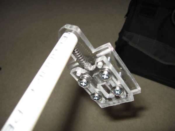
| Install a 1" length spring (one with a load between one and ten pounds) onto the catch plate and the set screw. |
Step Nineteen |
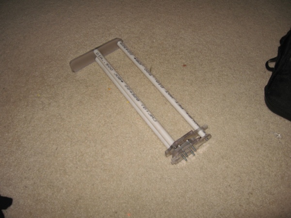
| Attach the 11-1/4" length sections of 1/2" diamter rod to both the rear frame piece and the butt stock using 3/8" length screws. |
Step Twenty |
| Slide the 12" length rod through the 1/2" hole in the rear frame piece and then bolt it to the butt stock using 3/8" length screws. |
Step Twenty One |
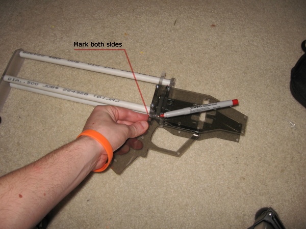
| Attach the side plates to the center and rear frame pieces using 3/8" length screws. Use one of the grip pieces as a template to mark the edges on both sides of the rear frame piece where shown. Using a 7/64" bit in a drillpress or power drill drill where marked to a depth of around 1/2 of an inch. Then tap the hole with a UNC #6-32 tapping bit. |
Step Twenty Two |
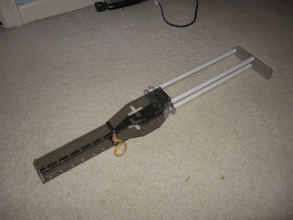
| Attach the front plates to the side plates using two 1/4" length screws, four 3/8" length screws, and two 1-1/2" standoffs. Wrap and tie a rubber band onto the standoff where shown. |
Step Twenty Three |
| Place the plunger cross where shown inbetween the 1" screws protruding from the front of the center frame piece. |
Step Twenty Four |
| Assuming you order exactly one foot of the 1-3/8" ID polycarbonate tube it should already be at the length you need. If not then use a mitre saw with box, table saw, band saw, or circular saw to cut a 12" length section from the longer tube. Slide the 12" length plunger tube onto the plunger cross and push it down to meet the top of the 1-1/2" standoffs. |
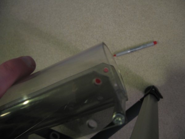
Step Twenty Five |
| Mark where shown. Using a 5/32" bit in a drillpress or power drill drill where marked on both sides. |
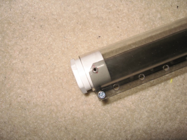
Step Twenty Six |
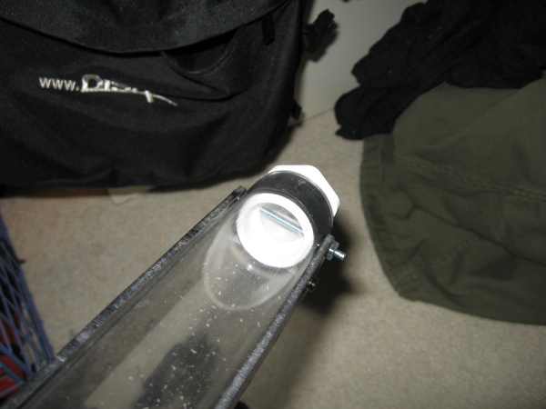
| Insert the hex bushing adapter into the end of the plunger tube and mark it as shown as well. You don't want to drill the holes in the hex bushing too far forward or it will prevent you from installing a barrel. Using a 5/32" bit in a drillpress or power drill drill where marked on both sides of the hex bushing. |
Step Twenty Seven |
| Wrap the hex bushing in 3 or 4 layers of electrical tape then use a hobby knife or ice pick to poke through the drill holes in its sides. Push it into the end of the plunger tube and line up all the holes. Lightly hammer then hand screw the bolt all of the way through and affix it on the other side using a lock nut. |
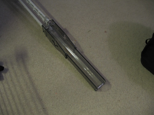
Step Twenty Eight |
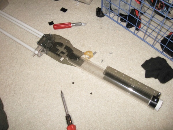
| Remove the new plunger tube assembly from the rest of the gun as shown. |
Step Twenty Nine |
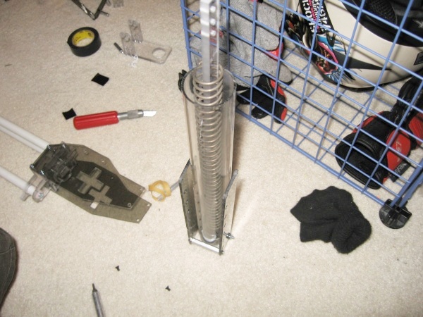
| Clean out the inside of the plunger tube then spray a generous amount of silicone lubricant into it. ONLY USE SILICONE LUBRICANT WITH PLASTICS. It's the only lubricant that won't eat away or degrade the material. Install the plunger rod and spring in the plunger tube. Work the plunger rod back and forth in the plunger tube a few times to get the o-rings lubricated. |
Step Thirty |
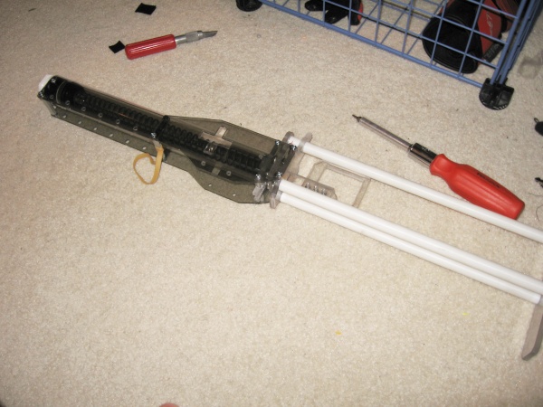
| While depressing the catch plate by hand, slide the plunger rod through the plunger cross, center frame piece, catch plate, and rear frame piece. Reattach the plunger tube assembly to the rest of the gun, starting with the 1/4" length screws. Attach the priming handle to the exposed end of the plunger rod. You can make and attach either one or two of these depending on your preferences. Other handle options are possible, but the other methods I've tried weren't as comfortable as this one. |
Step Thirty One |
| Use one of the grip pieces as a template for marking the 3/4" thickness polyethylene foam sheet. How much padding extends away from the grip is up to you, but 1/4" to 1/2" is plenty. Make sure to mark the two holes as well. |
Step Thirty Two |
| Finish marking like so and the foam shouldn't interrupt the trigger. Use a hobby knife or ice pick to stab out the holes. Use a band saw, hobby knife, scroll saw, or scissors to cut out the foam piece. |
Step Thirty Three |
| Follow the photograph labels for attaching the hardware to one of the grip pieces. |
Step Thirty Four |
| Slide the foam grip core onto the standoffs. Slide the trigger piece onto the 1-1/4" length screws and add another 1/4" length spacer. Install a 3/8" length screw in one side of the trigger. |
Step Thirty Five |
| Add a 3/8" spacer to the opposite grip piece. Put a washer and a lock nut on the end of both 1-1/4" length screws, but only tighten them enough for them to lock or the trigger won't slide. |
Step Thirty Six |
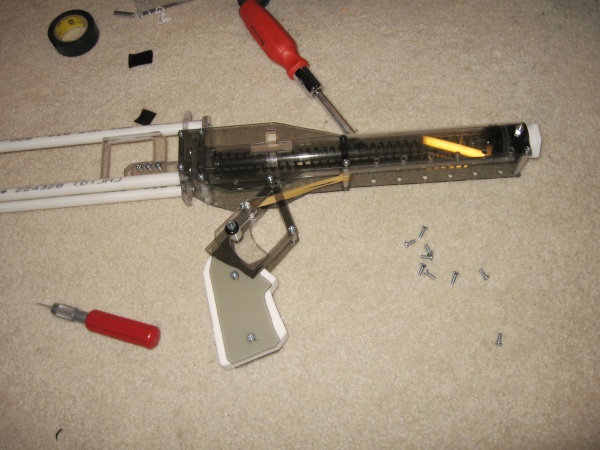
| Attach the front of the grip to the side pieces using 3/8" screws as shown. Hook the loose end of the rubber band onto the 3/8" screw you installed on one side of the trigger. Hinge the grip into place over the rear frame piece and attach it to both the rear frame piece and side pieces using four 3/8" screws. |
Step Thirty Seven |
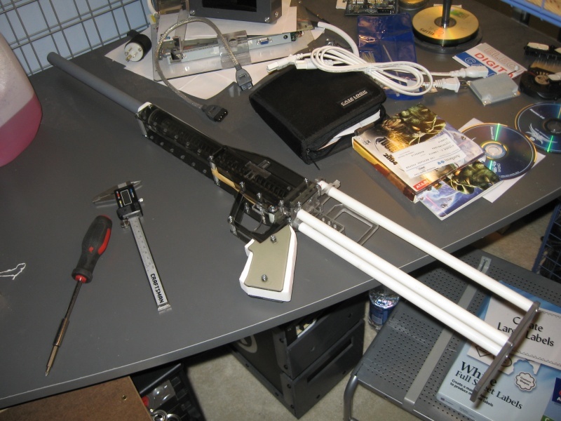
Add your preferred barrel, and your gun is now complete. The process has taken anywhere from 6 to 12 hours from start to finish depending on the tools you were using. Final Notes: + This gun is extremely durable, but in the rare event something does break it's not at all difficult toreplace any of the parts. + This gun doens't involve any glue. Hot, cold, or otherwise. So it should be able to take heat, cold, or humidity without any problems. + The rubber band on the trigger isn't a vital part and the gun will still function if it were to break. It's only there to improve the feel of the trigger and could just as well be replaced with a short/weak extension spring. I didn't have any on hand. |